Automated garden watering system

I like to work in the garden. For me, it's a great way to relax after an entire day of sitting in front of a computer. The last few summers have been getting a bit warmer and dryer around here in Belgium. I got tired of watering the lawn manually by gardening hose all the time, which is also rather wasteful if you forget to move the hose every 15 minutes or so. That's why I came up with the idea to build my own sprinkler system. But I had a few requirements to make it 'smart'.
Of course, any controller needs a way to schedule automatic activation. But to avoid wasting water, I also wanted to prevent activation of the system when it's raining or rain is expected. I also wanted the option to manually activate the system with the press of a button. I also needed to support multiple watering circuits, maybe for a flower watering circuit. And of course: it shouldn't cost a fortune! Since many existing controllers on the market are either too limited, would cause vendor lock-in or are too costly, I wanted to build something myself. Besides, where's the fun in just buying something off the shelf? This makes it a great project for me, as it combines programming, electronics, gardening, and some DIY skills.
I started by searching for sprinklers. To my surprise, you can already get a decent pop-up sprinkler that covers more than enough area for about € 12! Since my garden has a pond diagonally in the middle, the lawn around it has some complicated, sometimes narrow shapes. I went with the Rain Bird 3504, a smaller sprinkler which comes with a set of interchangeable sprinkler heads to adjust the radius from 4,6 to 10,7 meters. The angle is adjustable from 40 to 360°. A perfect sprinkler for my use-case, where I need to cover relatively small distances.
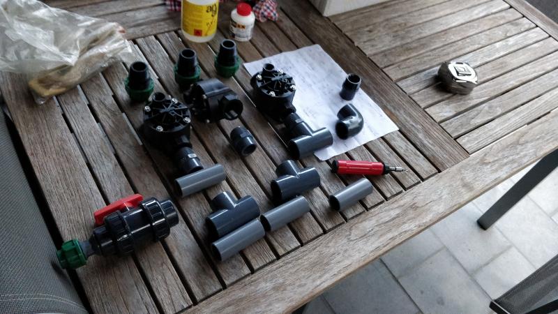
After planning out the layout of the system, I only ordered some sprinklers, tubing and connectors. I use PE (polyethylene) tubing of 25mm diameter, connected to knees and T-joints with compression coupling fittings and 1/2" outer thread. The tubes are connected with compression coupling fittings, which contain a rubber seal, while the 1/2" thread matches with the inner thread of the sprinklers.
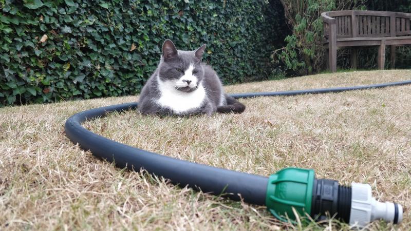
To start experimenting, I placed the sprinklers around the garden above ground, to be able to make modifications. This way, I could test whether the sprinklers were any good and how many sprinklers I could group on one circuit. Needless to say, the sprinklers exceeded my expectations! It was time to make the system smart.
Automating the system
Technologies
I wanted to use Home Assistant to control the system. I am not a fan of vendor lock-in, so I'm not that interested in any brand-specific automation platforms. Home Assistant is a free and open-source automation platform that is actively maintained by a very large community. The list of features and supported products is endless. You don't need any specific hardware, I chose to run it on a Raspberry Pi. I connected my Pi to the internet, so that I can monitor or activate my system from anywhere in the world!
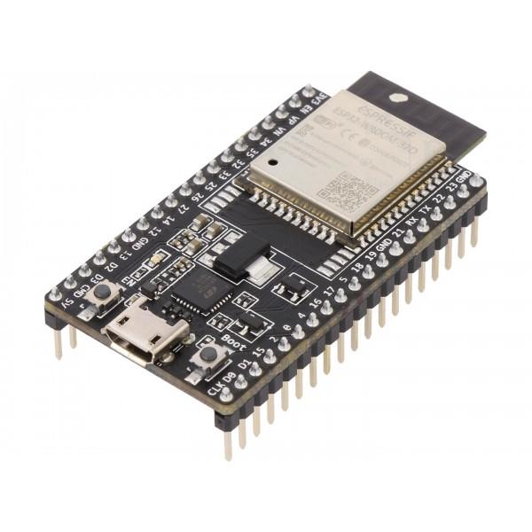
To control the flow of water to each sprinker circuit, I need a distribution board that can be wirelessly controlled. Since there's easy water access next to the garden shed, I decided to place the board there. This way, it's also located right next to the lawn so there's no need to run long stretches of tubing from inside the house. But since my Raspberry PI is running inside the house, I needed to talk to the distribution board wirelessly. That's why I needed some device with communication capabilities to act as a receiver for the commands from Home Assistant. I decided to use an ESP32, a microcontroller engineered by Espressif for mobile devices, wearable electronics and IoT applications. It contains integrated Wi-Fi, which was exactly what I needed. Since this is a one-off project, I didn't design a custom PCB. Instead, a development board was sufficient. I went with the ESP32-DevKitC-32D, which cost me only € 9! This board already contains everything I needed: plenty of GPIO pins, Wi-Fi antenna, programming and debugging circuitry via USB, power management, and a very extensive software stack to get started with.

Valves
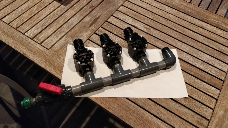
To switch the water flow going towards the circuits electrically, I went online to find electrical valves. Initially, I searched for a manual-like valve (that needs to be turned) with a motor on top, but that wasn't too commonly available. Instead, I learned about solenoid valves. I then found that Rain Bird offers valves like this as well, so I went with their 100-HV model. These are valves which contain a rubber membrane that get opened by means of an electromagnetic force from a solenoid. While the solenoid is not being powered, the water pressure keeps the membrane shut, while powering the solenoid allows a tiny bit of water to pass through to the other side, allowing the pressure balance to change and an opposing force will be exerted on the membrane to open the valve. See the video below. These valves are controlled by 24 VAC and are pretty cheap (€ 25).
Power supply
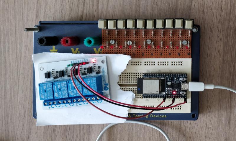
To power both the valves (24 VAC) and the ESP32 (5 VDC) with the same power supply, I bought a transformer (Triad Magnetics FD6-24) with a split secondary winding, providing access to 24 and 12 VAC when connected to 230 VAC mains voltage. The 24 VAC could then be directly routed to the valves, while the 12 VAC needs some further rectification and filtering to create a steady 5 VDC. Therefore I quickly soldered a PCB together with a bridge rectifier, a 470 µF electrolytic capacitor and a 0.1 µF ceramic capacitor. I could then add a simple 7805 voltage regulator to create a stable 5 VDC, but since the input voltage was still on the high side, this would produce a lot of heat. To avoid wasting energy, I used a buck converter, in this case a pre-built board from Velleman, the VMA404, which is based on LM2596S. This board can regulate the power in a more energy efficient way.
Relays
I added a relay module (Velleman VMA400) to switch the 24 VAC voltage going to the valves with the lower DC voltage supported by the ESP32. But since the load connected to the relays (the valves) is inductive, I also wanted to add some varistors to discharge transient voltage spikes. This is important to extend the lifespan of the relays.
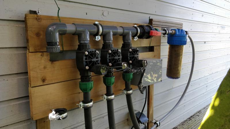
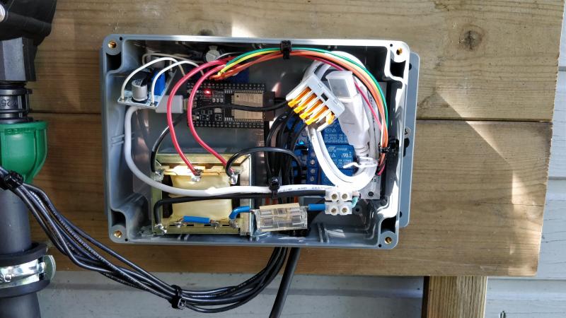
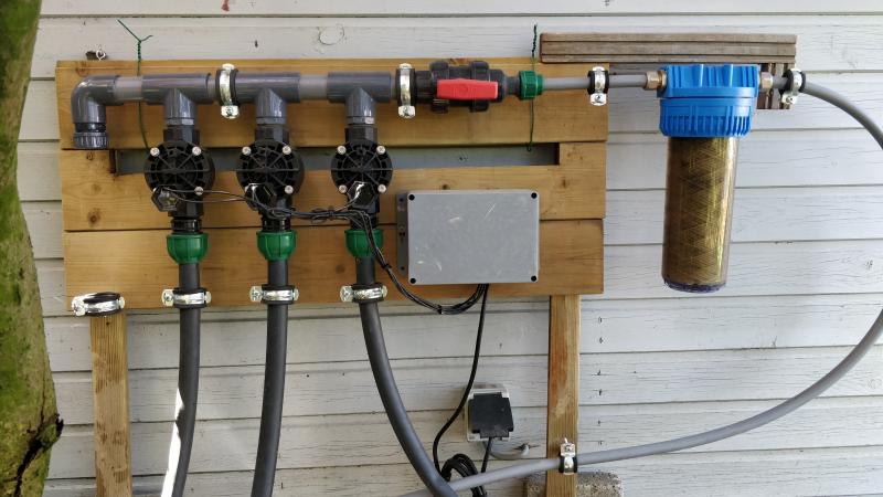
Adding some glue
Now it's time to bring all components together. I mounted everything on a wooden frame, this makes it easy to 'winterize' the system and bring everything inside. The water is fed into the system on the right, where I also added a dirt filter to avoid leaky valve membranes. When the manual shut-off valve is open, the water flows into the inlets of the valves. I put all the electronics in a waterproof enclosure.
Programming the firmware
To get started with programming on the ESP32 there are multiple options. The official development stack is called ESP-IDF and is a set of libraries written in C. When comparing it with other embedded development technologies, it's fairly easy to use, the framework has some very readable API's and is well documented. There are also Arduino libraries, that allow you to program the ESP32 with Arduino code. But since I wanted to have full control, I decided to use ESP-IDF to build the firmware.
To communicate with the ESP32 board, I considered a few options. First, I tried to host a REST API on the ESP32 allowing Home Assistant (or any other device) to send valve open/close requests to the board or ask for the current valve status. This worked, but a fully fledged HTTP stack is pretty heavy for an embedded device like this. Especially when you're trying to use HTTPS... The very basic HTTP server library I implemented would often crash the program when sending it something I didn't quite prepare it for. And with HTTP, there are a LOT of things you can throw at a server.
That's why I switched over to MQTT. This is much more lightweight protocol which is better suited for IoT devices like this. MQTT is a publish/subscribe system that allows devices to communicate via a message broker. The broker is a central server that all clients connect to. It regulates the traffic, and decides which messages should be forwarded to which clients.
To route messages, clients connected to a broker can publish messages onto a certain topic. A topic is identified by a string that describes the kind of messages that will be transmitted there. It's a way of grouping messages of the same kind together. Clients can then subscribe to one or more topics to receive the messages from the broker. If a client isn't interested in a particular topic, it can decide not to subscribe, and won't receive the messages. This makes it a pretty efficient protocol.
Luckily ESP-IDF supports MQTT out of the box! The libraries are very easy to use. See some of the examples here.
As a message broker I decided to use Mosquitto and installed it on my Raspberry Pi, where Home Assistant is also running. I decided to use the topics "wateringcontroller/valve/[index]/status" and "wateringcontroller/valve/[index]/switch". The index will be a number from 0 to 3, as I will support four different valves. The switch channel will be used to publish open or close commands to, and the status command will contain feedback about the current state of the system. This means that Home Assistant will be publishing to the four switch topics, and our ESP32 will be subscribed to these. When receiving a request, the roles are reversed and the ESP32 will publish a confirmation message to one of the status topics. Home Assistant can then subscribe to these messages to display the actual status of the system. In case of a connection failure, the user now has some feedback!
Using MQTTfx, I can monitor what's being transmitted:
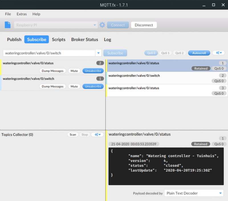
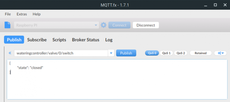
Here, I am monitoring both the switch (cyan) and the status (yellow) topics of the first valve (index 0). The oldest message with id 3 was posted to the status topic and notified me that the valve was open. I then sent a close request to the switch topic. I have catched this message as well (id 2). Subsequently, the ESP32 answered with the status message on the status topic (id 3). The output can be seen in the panel below.
You might notice the "Retained" flag next to the most recent status message. If messages are published with a RETAIN flag, the MQTT switch will receive an instant state update after subscription, and will start with the correct state. Otherwise, Home Assistant cannot know the current state unless the ESP32 transmits it again. That's why I always retain the most recent message on every status topic.
Talking to our IoT device
This is the fun part. Home Assistant makes it really easy to talk to devices using MQTT. They provide a number of components, including one especially for the purpose of turning things on and off: the MQTT Switch. This component allows you to set a state_topic and a command_topic. The state_topic will be used to subscribe to and receive updates about the current state of the system. The command_topic will be used to publish requests to, when the user flips the switch (or it could be an automation or script!).
But how does Home Assistant know what to send to the device? And how can it understand its output? That's where the payload_on, payload_off and the value_template parameters are for. These allow you to define how Home Assistant should send requests or parse the output. How convenient, right?
My configuration looks like this:
switch:
  - platform: mqtt
    name: Rain Birds (right side)
    icon: "mdi:water"
    command_topic: "wateringcontroller/valve/0/switch"
    payload_on: '{"state": "open"}'
    payload_off: '{"state": "closed"}'
    state_topic: "wateringcontroller/valve/0/status"
    value_template: '{{ value_json.status }}'
    state_on: 'open'
    state_off: 'closed'
    optimistic: false
This produces the following switch in my Home Assistant interface:

The blue water drip will turn yellow when the system reports that the valve is actually opened. It always waits for the system to report the change, it won't decide to just follow what the switch does. In case there was a problem switching the valves, after a few seconds the switch will even reset itself into the correct state!
That's everything needed to control the system with Home Assistant. No programming required on this end!
Automating
Now that I have complete manual control over the valves, it was easy to automate this. Home Assistant makes it simple to schedule this process every evening, 1.5 hours before sunset.
automation:
  - alias: 'Automated garden watering schedule'
    trigger:
      - platform: sun
        event: sunset
        offset: '-01:30:00'
    condition:
      - condition: state
        entity_id: automation.automated_garden_watering_schedule
        state: 'on'
    action:
      - service: script.garden_watering

script:
  garden_watering:
    alias: Manually start garden watering
    sequence:
      - alias: Notify start of garden watering
        service: telegram_bot.send_message
        data:
          message: "Watering system started!"

      - alias: Rain Birds (right) on
        service: switch.turn_on
        data:
          entity_id: switch.rain_birds_right

      - delay: '00:{{ states.input_number.rain_birds_right_duration.state | int }}:00'

      - alias: Rain Birds (right) off
        service: switch.turn_off
        data:
          entity_id: switch.rain_birds_right

      - alias: Notify end of garden watering
        service: telegram_bot.send_message
        data:
          message: "Watering system was turned off!"
This automation triggers a script that will turn on all the valves one by one (in this example there is only one valve). The time in minutes between every cycle can be set with sliders. See the screenshot below. With Home Assistant it is also a piece of cake to add notifications to your scripts. I expanded this script to notify me 10 minutes ahead of time. This lets me know whether the system will turn on today or not, even while I'm away!
Another major goal of this project is to be able to make smart decisions based on weather prediction. This is also very easy in Home Assistant, thanks to the numerous available weather services I can read the precipitation data that is expected to fall today or tomorrow. With a bit of fine tuning with the precipitation intensity values, I was able to set a certain threshold to decide whether or not to turn on the system today.
During winter, it's very easy to turn off the scheduling system. All I need to do is to turn off the automation, which Home Assistant already provides a switch for.
I would really recommend to check out ESP32 and Home Assistant. Projects like these are a lot of fun!
Comments ()