Stewart platform racing simulator
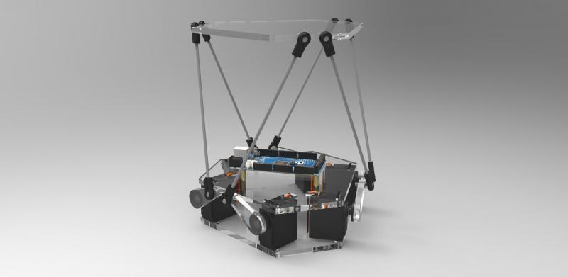
To obtain my degree in Industrial Sciences at VTI Waregem, I had to do a final project (Geïntegreerde Proef or GIP) with a co-student. Because we didn't like the idea of only writing a theoretical paper for a whole year, we went online and started our quest for an interesting technical challenge to research and build.
We were attracted by motion simulator projects based on a Stewart platform. A Stewart platform is a type of parallel manipulator that is able to move and orient a platform with six degrees of freedom (DoF). They are used not only in racing simulators, but also in full-scale flight simulators, 3D printers, milling machinery, ocean wave simulation, satellite dish positioning, and even in space, to dock vehicles to the ISS.
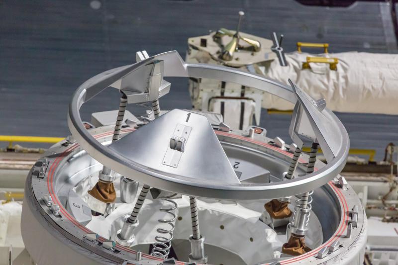
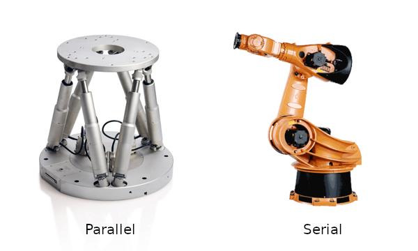
A Stewart platform is a mechanical construction which consists of six independently controllable hydraulic or electromechanical cylinders, which are connected to a fixed base and a movable platform. By controlling the length of each cylinder, the platform can be moved precisely with six degrees of freedom: three linear movements over the x, y and z-axes, and three rotational movements. It is a type of parallel robot, a system which uses multiple independent computer-controlled robotic arms to position a single object. This is in contrast to a serial system, where the robotic arms are chained to each other and work dependent of each other. Because the system uses six cylinders, the system is often called a hexapod, or a 6 DOF (degrees of freedom) motion platform.
For some applications, the cylinders can be replaced by a system with rotary servo motors. These motors can be set at a specific position. If one makes use of servos instead of the more common system with cylinders, the cylinders are replaced by rods with a fixed length, which are connected using ball joints to the arm of a servomotor, mounted on the base. This is a cheaper alternative for small scale projects, but the platform is limited in traversing relatively long distances because the rods are mounted on a relatively short radius from the center of the motor. The movements can be very accurate as well, because these motors also contain a feedback system to counteract the positioning error.
Due to the complexity of the system, most of the work went into understanding the mathematics to correctly position a platform. Given a set of orientation parameters, the mathematics have to accurately calculate the position of the actuators to achieve a desired orientation.
Designing the platform
Our goal was to design and build a small-scale Stewart platform for a racing simulator. We've used rotary motors because they are cheaper, since there was no financing for this project. We were inspired by the design of the miniature simulator from Full Motion Dynamics, so we decided to also build it out of plexiglass. We started by drawing out our parts with Solid Edge:
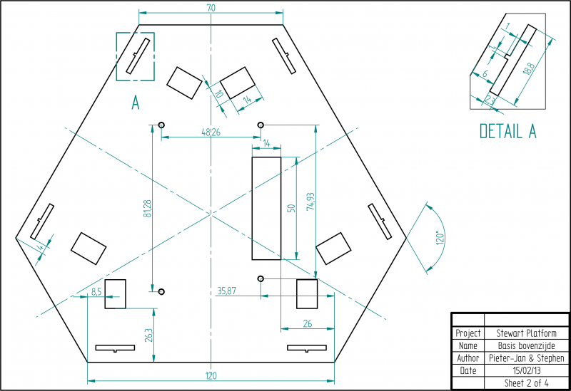
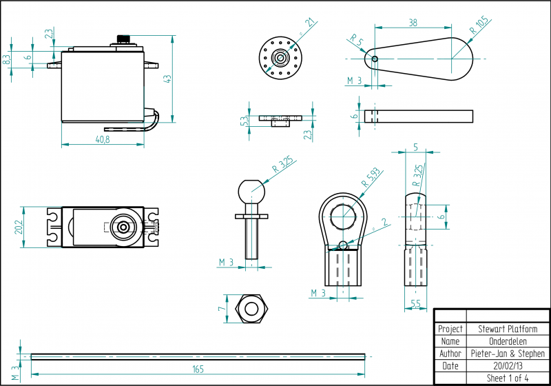
By designing it with CAD software, we are able to see better what the platform would eventually look like, and check the range of motion that would be possible with its dimensions.
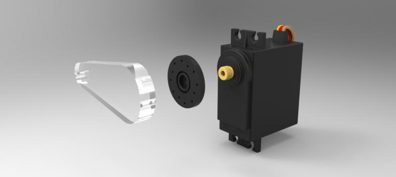
To drive the platform, we used some very cheap off the shelf servo motors, which turned out to work great. They had more than enough power and speed for our needs. They also came with plastic adapter parts that made it really easy to screw our plexiglass arms onto.
Driving the platform
The platform is controlled by our software written in C# which is responsible for all the mathematics to position the motors. The calculations are performed on a computer to have plenty of processing power at our disposal. Our program then sends the results to an Arduino Mega via a serial-over-USB connection, which in turn positions the servo motors using PWM. While this offloads the Arduino greatly, this also had the benefit of being able to display a 3D visualisation so we could work on the software without being connected to a physical platform.
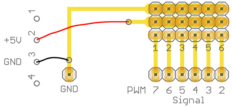
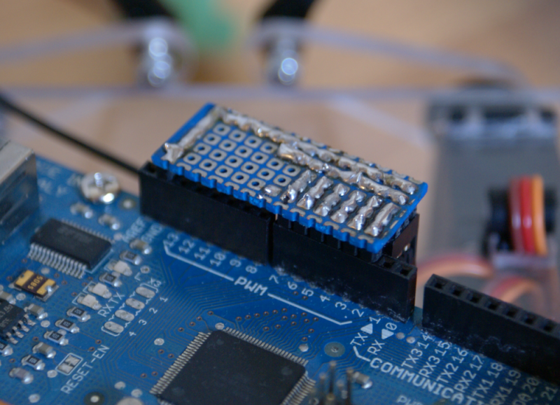
The motors are powered by an external modified ATX PSU (to bring down the costs). To connect the motors more easily to the Arduino, we built a mini PCB with pin headers. This way, connecting the motors becomes only a matter of plugging the connectors into the board.
Making it move!
To make our software universally usable, we built a variable platform configuration system. Platform dimensions and coordinates can be entered and exported to XML config files to be used later. Both linear and rotary actuators are supported.
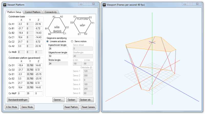
With the program you can control the platform manually by modifying the 6 DOF parameters. We've also programmed a 3D simulation (using DirectX), so you can see the results in real-time.
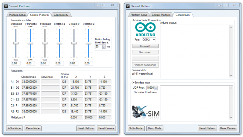
But instead of controlling the platform manually, the program can also take input from other sources. For our practical application as a miniature racing simulator, we've used http://www.x-sim.de to extract real-time motion data from games. Our program takes this data as its input and moves the platform accordingly. This simulates the G-forces you would experience if you'd be inside the car.
For fun, we also connected X-Sim to Flight Simulator:
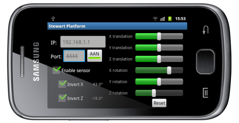
We've also developed a small Android app that can remotely control the platform manually or using the phone's accelerometer.
Comments ()